|
|
 |
|
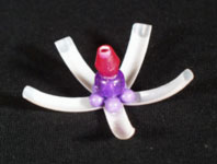
SKETCH 06 (left): This sketch marked a turning point in the design as it established the syringe's body style.
|
|
|
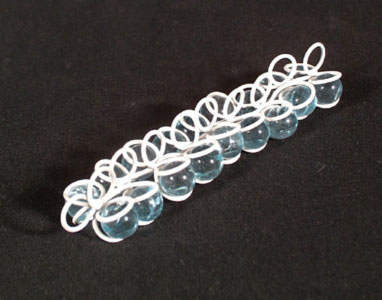
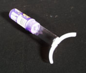
SKETCH 02 (right): This sketch was Tyson's response to the project directives specification for incremental fluid dispensation.
|
|
|
 |
|
|
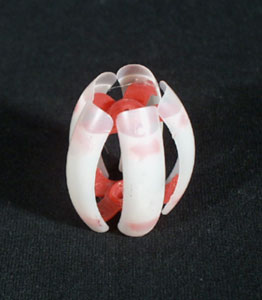
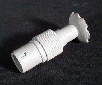
SKETCH 03: These "petals" gave the illusion of turning or twisting—a movement which became a key element in the final design.
|
|
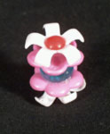
SKETCH 04: The fact that this sketch seemed to close upon itself was another important and exciting option explored later in the design process.
|
|
|
|
|
|
|
|
|
 |
|
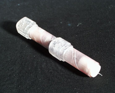
BUCK 01 (left): Shows mechanical workings and possibilities.
BUCK 02 (above): Helped determine fluid pathway.
BUCK 03 (right): This model actualized the final mechanics of the syringe.
|
|
 |
|
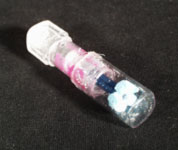
BUCK 06: Mechanical actualization for deployment & capture of fluid.
|
|
 |
|
|
CONCEPT 01 (left): Board detailing attributes of an alternate concept for the syringe.
|
|
|
SIZE & CHARACTERISTICS (right): Board detailing attributes of final concept for the syringe.
|
|
|
 |
|
 |
|
|
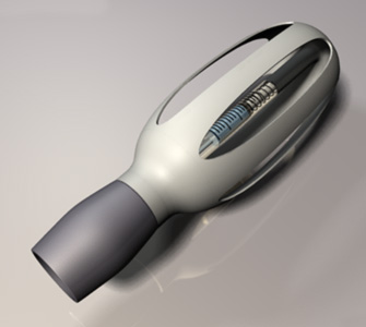
FINAL REALIZATION (left)
|
|
|
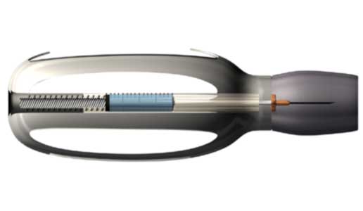
CUTAWAY VIEW (right): An image used to illustrate the mechanics of the design.
|
|
|
 |
|
 |
|
|
DEMONSTRATION OF CONCEPT ONE (top right)
|
|
|
EXPLODED VIEW (left)
|
|
|
DEMONSTRATION OF CONCEPT TWO
(bottom right): The selected final concept.
|
|
|
|